If you’re going to design embedded hardware you have know your way around the most common wired digital communication protocols and standards. These protocols and standards define how different parts of an embedded system communicate with each other, for instance how a sensor or an actuator communicates with a microcontroller.
This whole post encompasses only digital communication standards. In addition you have the more basic analog or PWM signal methods which are also used to communicate between devices, but we won’t talk about these today.
Serial vs Parallel
There is a huge variety of protocols and standards to choose from, all with their advantages and disadvantages. The two main types of wired digital embedded communication are serial and parallel.
Parallel
Parallel communication is very basic, easy to implement and has a fast transfer rate. However, it uses as many data wires as the bit width (sending 8-bit messages will require eight data wires). This quickly adds up to quite a lot of wires, which is less than ideal when working with microcontrollers with a limited amount of pins. If you for instance want to transfer 8-bit ASCII values you need eight wires for the data, a common GND, a clock wire for synchronous transmission (which we’ll talk about later) and other dedicated wires for any other signal you want to transfer.
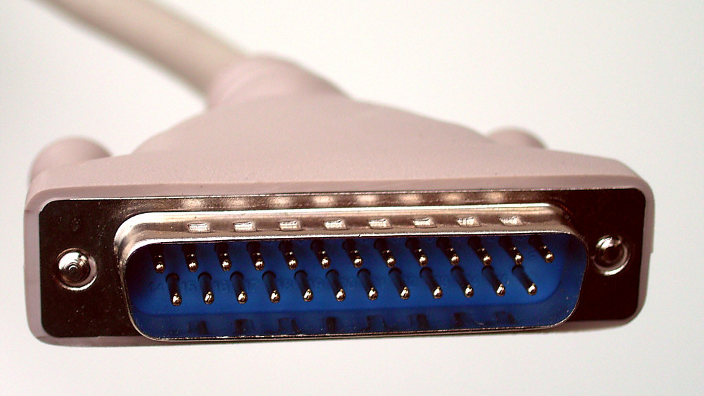
The DB-25 parallel port has a total of 25 pins where only 8 pins are data pins, 8 pins are GND and 9 pins are other signals not directly related to the data transferred.
Another drawback with parallel vs serial is that you get interference between the lines with long cables. You can usually have longer cables with serial communication than parallel.
Even though parallel communication has a whiff of that old school smell surrounding it, it is widely used today in many areas such as computer technology and industry.
Serial
This is the type we’re going to dig more into in this post. This is because serial communication is much more relevant for the average maker than parallel.
Microcontrollers usually have built-in HW-modules aka. peripherals which handle serial communication such as UART, SPI and/or I2C. These are the three types of serial communication we’ll examine in more detail.
However, before we get to that we need to talk about the difference between synchronous and asynchronous transmission.
Synchronous vs Asynchronous Transmission
Synchronous standards have a dedicated clock wire to synchronize the devices which are communicating. Within the specific protocols the devices know what data is being sent and/or received at any given time.
On the other hand you have asynchronous transmission. Here you need something else to define the start and stop of a packet (e.g. start and stop bits). The devices communicating asynchronously need to have a roughly (relatively speaking) similar perception of time (defined by baud rate or clock frequency). Start/stop bits often are usually held longer than data bits such that they are differentiated from each other. One advantage with asynchronous transmission is that you of course have one less wire to worry about.
UART
Universal Asynchronous Receiver/Transmitter, aka. UART, is a common HW device or microcontroller peripheral which enables asynchronous communication (you also have specific UART chips).
UART is usually used in one-to-one scenarios (i.e. only two devices communicating with each other), it’s full-duplex which means that a device can send and receive at the same time, and as its name implies it is asynchronous.
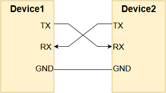
In its most simplistic form UART consists of 3 pins:
- TX (transfer)
- RX (receive)
- GND (for a common voltage reference, implicitly included in the next chapters)
The TX is the transfer pin and RX is the receive pin. The schematic below shows how to usually connect two devices using UART.
UART is often used to implement simple custom transfer protocols. Remember that UART doesn’t strictly define how bits or bytes should be transferred. It’s more of a generic HW interface used for serial communication.
USART
USART (Universal Synchronous/Asynchronous Receiver/Transmitter) is basically an extension of UART where you also have the option for synchronous transmission with a dedicated clock wire. USART instead of plain UART has become pretty common on board modern microcontrollers.
RS-232 and Friends
RS-232, RS-422 and RS-485 are some of the serial communication standards that use UART. These standards define the wiring and electrical properties of the signals such as voltage levels, speeds, pinout, termination resistors, robustness and a lot of other things. These standards often use more wires than TX/RX. Not for data, but to ensure safe transmission (e.g. handshaking signals such as Request To Send and Clear To Send).
SPI
SPI (Serial Peripheral Interface) is a different serial communication interface than UART. It is more strictly defined, synchronous and supports multiple devices. However, just like UART it’s full-duplex.
The whole scheme is based on a master/slave architecture where you have one master who’s the boss and initiates every transmission (e.g. a microcontroller), and one or more slaves who do as the master says (e.g. sensors or LCD displays).
Instead of (and in addition to) TX and RX you have:
- MOSI (Master Output, Slave Input)
- MISO (Master Input, Slave Output)
- CS (Chip Select) aka. SS (Slave Select)
- SCL aka. SCLK (Serial Clock)
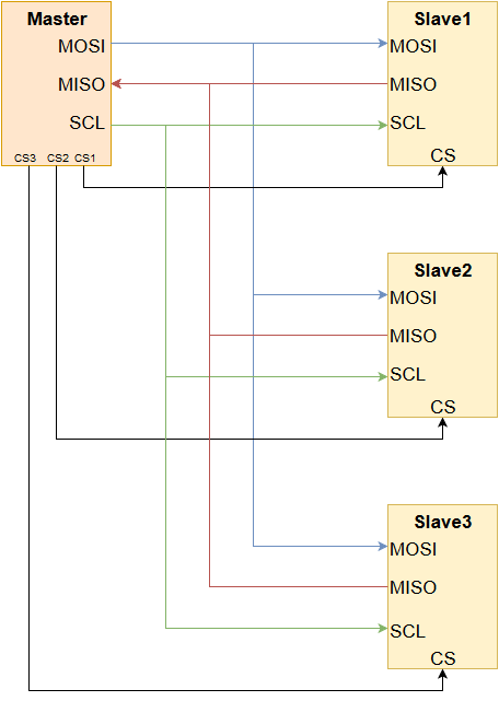
MOSI and MISO are the data lines. MOSI is for data from the master to one or more slaves and MISO is for data from one slave to the master. Since all slaves share the same MOSI and MISO lines it is important that they don’t try to transfer data to the master at the same time. CS is used by the master to select which slave it wants to communicate with. This ensures that only the correct slaves receive messages and also that the slaves won’t transfer data at the same time. SCL is the clock used for synchronizing the signals, so things like start and stop bits aren’t necessary. In addition to all these wires you also need a common GND for voltage reference.
One important disadvantage with SPI is that it requires one CS pin per slave. There are scenarios that uses the SPI interface with shift registers and many slaves (such as individually controllable LEDs) in series instead of parallel to omit the need for a buttload of CS pins. However, this is a grey area regarding the actual definition of SPI.
I2C
I2C (Inter-Integrated Circuit) is another common interface for serial communication. It has several similarities with SPI: it has a master/slave architecture with support for multiple slaves (as well as multiple masters!) and is synchronous.
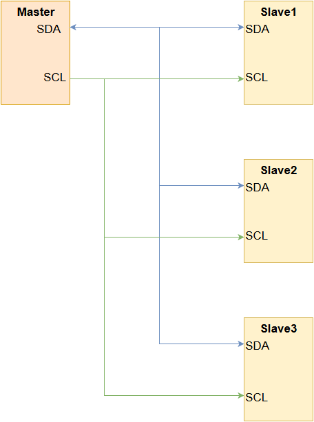
One of the biggest advantages compared to SPI is the absence of the CS pin(s). Instead, I2C uses addressing to reach specific slaves. I2C supports 127 different addresses on a single bus, so in theory you can connect 127 devices together. However, the addresses are often hardcoded into the device, so an address conflict is almost guaranteed to occur before reaching 127 different devices.
Another difference is that I2C is only half-duplex. While this might be a disadvantage in some areas, you only need one data wire. This results in only two wires in addition to a common GND:
- SDA (data)
- SCL (clock)
I2C is not as fast as SPI and it can be a bit more complex to implement. However, it uses fewer wires and is more suited for many connected devices. It also supports multiple masters.
Note that many datasheets refer to I2C as TWI (Two Wire Interface). This is only for trademark reasons and the two are equivalent.
Wrap-up
If you initially didn’t know much about digital serial communication we hope reading this post gave you a better overview of it. Remember that this post barely scratches the surface of the topic. It is a very large field of study with a lot of electrical considerations, different protocols and intricacies in general. We might go more in depth on the specific standards/protocols in the future.