Let’s continue our introductory journey through different electronic components. Previously we’ve looked at capacitors and inductors. We’ve also looked at potentiometers, buttons and temperature sensors in conjunction with the Arduino.
This time we’ll take a quick look at transistors and relays.
The Basics
The Similiarities
The reason we’re going to look at these two types of components in the same post is that they often basically do the same thing. They both work as electronic switches. Instead of a finger pusing a button they react on an electric signal. Most commonly they don’t let current through before they get some voltage on a control terminal (some work the opposite way, of course).
The Differences
Even though the basic functionality is similar the applications for the two is often very different.
Transistors
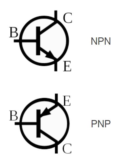
Transistors usually have three terminals, two for current in and out and one for control. What these terminals are called depends on the type. There are two main types of transistors: BJT and FET, with each having several subtypes.
Transistors are usually cheap and can be extremely small. They don’t have any mechanically moving parts, so they can switch on and off very quickly. With many transistors connected together you can create a logic circuit. And with an insane amount of insanely small transistors connected together you can make computer parts like CPUs and SSDs. See the video below to get an impression of the transistor size used in microchips.
In a previously written post about DC Motors we go through an example where we utilize a transistor as a switch.
Disclaimer: dry tech-talk incoming! Feel free to jump to the next paragraph 🙂
When doing research around transistors you will find a lot of talk about NPN and PNP transistors, which can be quite cryptic. These are subtypes of the BJT transistor family. The main difference between NPN amd PNP is that NPN transistors need a digital HIGH to be “turned on” while PNP transistors need a digital LOW to be “turned on”. As a rule of thumb you should place NPN transistors close to GND and PNP transistors close to Vcc or equivalent.
Another application where transistors can be used is as amplifiers (as opposed to switches).
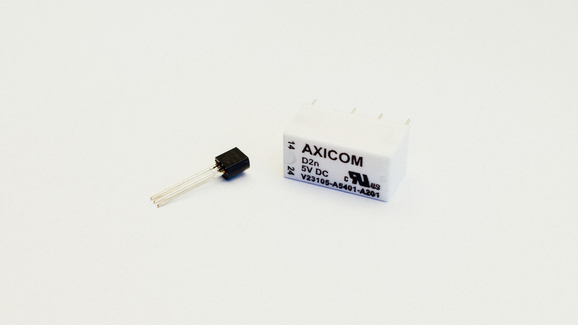
Relays
The traditional relay is an electromagnetic switch. There are many different types of relays. A common type of has have two pairs of terminals (or more) where current through one pair of terminals closes a switch between the other pair of terminals.
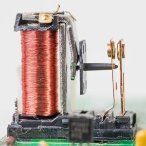
One major advantage with relays is that the two pairs of terminals are completely seperated (galvanically isolated). If large currents will flow without frequent or fast switching, the relay is often the component of choice.
That clicking sound you hear when turning on the turn signal on (at least) old cars is the sound from a relay switching on and off.
You also have Solid State Relays (SSR) which work as mechanical relays except they don’t have any moving parts. So here you get the galvanic isolation without the mechanic limitations: the best of both worlds! SSRs usually use an optical sensor and an LED instead of a mechanical armature. They are usually much more expensive, though, and they only work as switches while transistors can be used as amplifiers as well (as previously mentioned).
Example with Both a Transistor and a Relay
Sometimes you need both transistors and relays in a circuit.
Let’s say you have a DC motor (M1) which requires a lot of power. You want to control this with an Arduino or some other microcontroller. The power required to run the motor is too large for your every-day transistor to handle, so you figure a relay (RY1) is the way to go.
However, you don’t want to draw the current required to drive the relay directly from the GPIO-pin on the microcontroller (as this can harm the microcontroller) so you decide to use a transistor (Q1) instead. Q1 is in this case a PNP transistor which need a digital LOW to let current through. Be sure that Q1 can handle the current that will flow through RY1.
Vcc is typically the same voltage that drives the microcontroller.
R1 is there to limit the current passing through the microcontroller port since some current will “leak” through the control pin of the transistor.
Last, but not least, we have D1, which is a flyback diode. We go through why we use flyback diodes in this post. The relay has a built-in inductor (read this post for an intro about this component), which don’t like changes in current. So when you turn off the transistor, the inductor will continue to draw current which might damage the transistor. By using a flyback diode this current will be “extinguished” in the small D1–RY1 circuit due to circuit resistance instead of damaging the transistor.
The resulting circuit is shown below:
![]()
To summarize: the microcontroller will make current flow through the transistor and thus the relay. This creates a magnetic field in the relay which closes the internal relay switch. As a result of this, the motor-circuit is closed and current flows through the motor making it spin.
Concluding Words
Transistors are used in a whole bunch of different applications. We could’ve talked more about the amplifier-usage of transistors, but we’ll save that for another day. The size of microchip-transistors is simply mind-blowing, but in essence they do the same as their much larger siblings.
Relays are more one-sided in their applications, but definitely have some advantages over the transistors.
The most important thing is to choose the right tool for the job!