A couple of weeks ago we wrote a post about capacitors. This time we’re going to look at the capacitor’s relative: the inductor. Throughout this post we’ll compare the two from time to time, so it might be a good idea to look at the capacitor post if you’re not familiar with them.
What Is It?
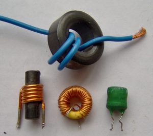
The inductor is arguably simpler in its physical construction than the capacitor. It is basically just a coil of wire wound around an iron or ferrite core (these are called ferromagnetic core inductors) or around non-magnetic cores such as ceramic, plastic or just air (these are called air core inductors). Just like the capacitor it has two terminals and is completely passive.
How Do They Work?
At first glance this electrical component might seem completely pointless. What makes it useful is electromagnetism. The inductor stores energy in a magnetic field in the coil (if you recall, the capacitor also stores energy). The current through an inductor never changes instantly. When current starts flowing through the inductor the magnetic field starts to build up and during this phase the current will gradually increase. When zero voltage is applied to the inductor the current will gradually decrease while the magnetic “storage” empties itself.
An inductor’s size or capacity is determined by the number of windings, the core material, the cross-sectional area of the coil and the length of the coil. All these parameters results in a certain inductance. The standard unit for inductance is henry (H).
Energy stored in inductors comes out the same direction as it went in while energy stored in capacitors comes out the opposite direction as it went in.
Remember the equation we included in the capacitor post?

Here’s the equivalent equation for inductors:

You probably see the similarities between these equations. L is the inductance of the inductor.
This equation shows that it will be a voltage difference between the inductor’s terminals when there is a change in current through the inductor. The quicker the change and the larger the inductor, the larger the voltage difference.
An Example
To show you how this works in practice, let’s take a look at the following circuit:
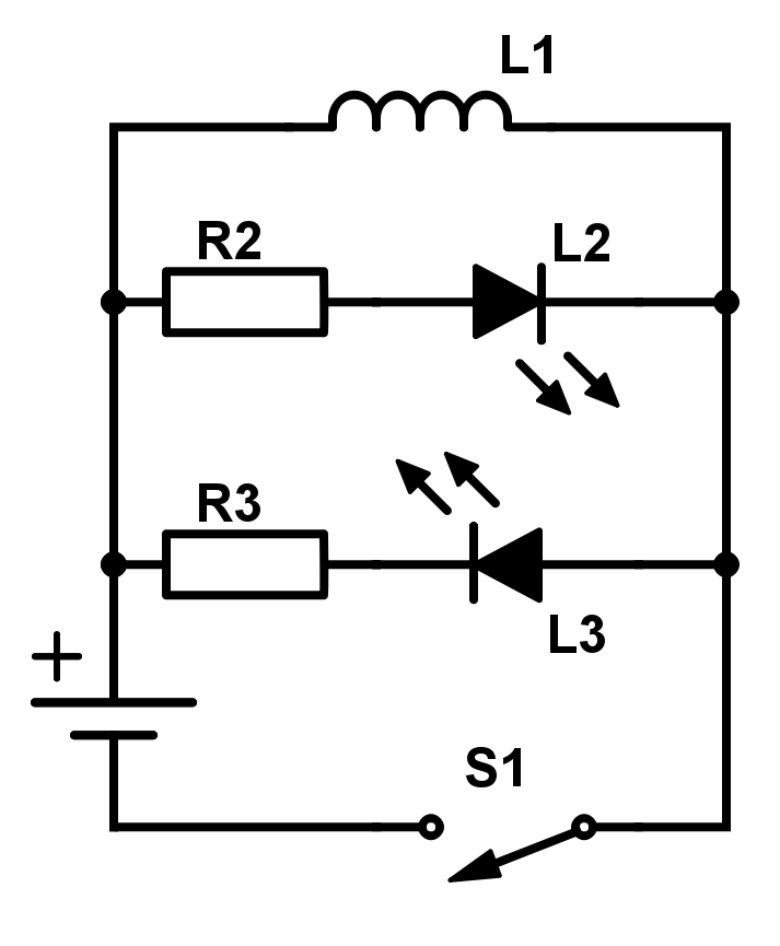 L1 is our inductor (relatively big for demonstration purposes). L2 and L3 are LEDs while R2, R3 and S1 are resistors and a switch, respectively.
When the switch is closed after being open for a while, the following will happen:
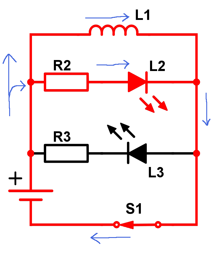
- The LED L2 will light up. All the current will initially flow through R2 and L2.
- As more and more current flows through L1, less and less current will flow through the LED making it fade out.
- Once the current reach a steady state, most of the current will flow through the inductor instead of the LED because of the resistor R2. The current ratio between the inductor and the LED depends on the size of R2 and the resistance in L1.
When the switch is opened after being closed for a while, the following will happen:
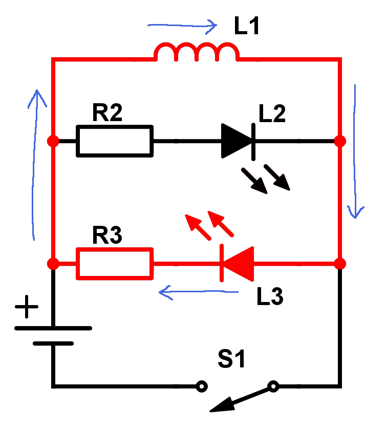
- The magnetic field in the inductor will ensure that the current will continue in the same direction as it was (clockwise). The LED L3 will initially light up since all the current supplied from the inductor will move through L3 and R3.
- The current, and thus the LED birghtness, will decrease as the inductor discharges.
- When the inductor is completely discharged, no current will flow in the circuit.
Where Are They Used?
Inductors are common components used in filters, power supplies and oscillators (together with capacitors).
They are also dug into the tarmac in traffic light intersections. When a car moves on top of an inductor all the metal affects the magnetic field which changes the inductance. This results in a simple and elegant “car-sensor”. This is why you often need to wait for a car to get a green light when you’re out road biking.
To Summarize…
An inductor stores energy in a magnetic field and works “similarly, but opposite” of the capacitor. You can look at the inductor as an angry fellow who doesn’t like change in current. He will do his best to combat changes in current with the power of his mighty (or not so mighty) magnetic field.
Stay tuned for more basic intros on electrical components in the future!