Before this year’s Maker Faire in Trondheim we in NC wanted to make an interactive installation to our stand. With a short deadline, we didn’t have time to order everything we needed. So we searched through what we had laying around and used what we could find of value for this project.
Remember to also have a look at our previous post about this project where we show you graphs and stats from the two days at Maker Faire!
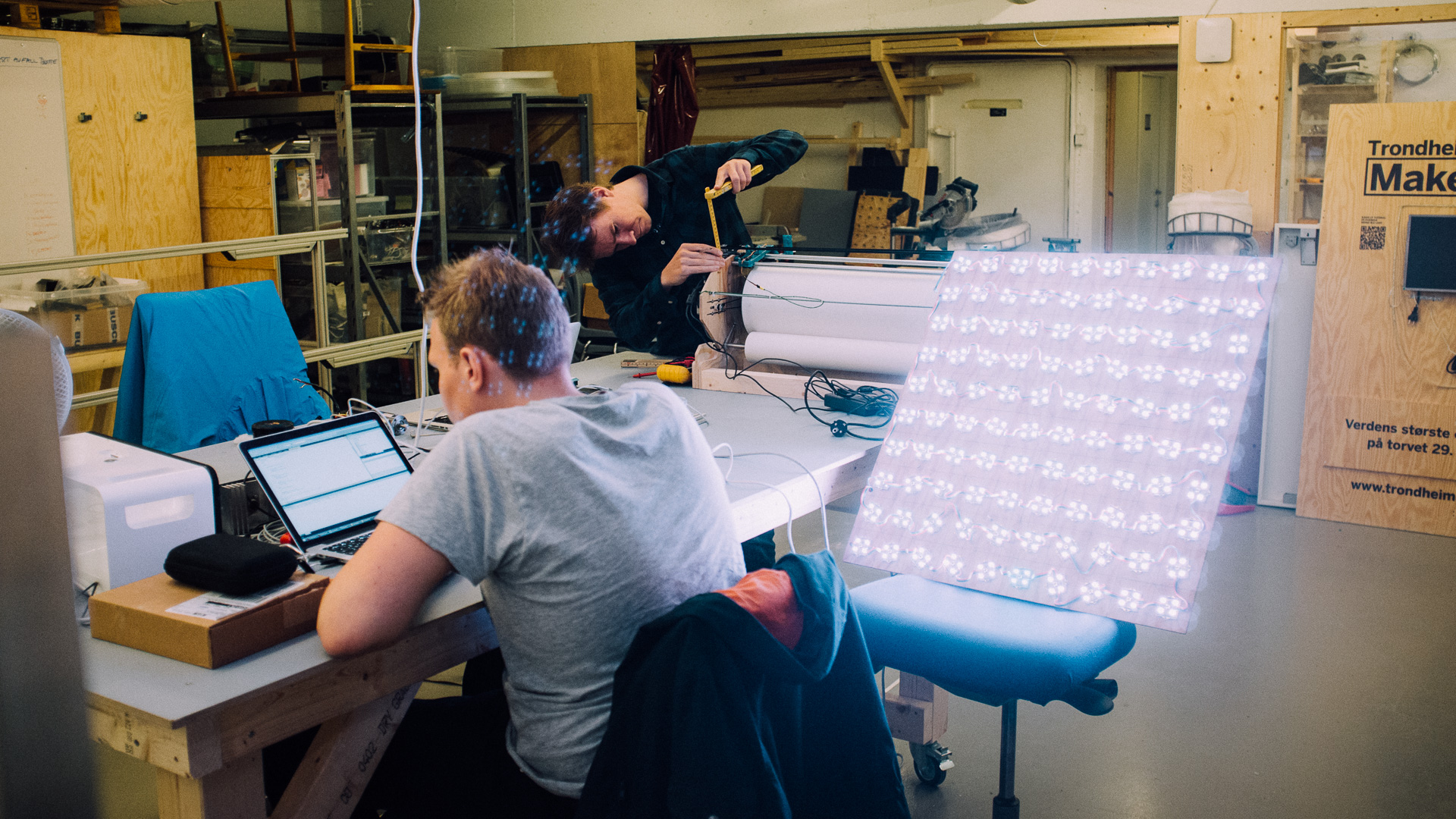
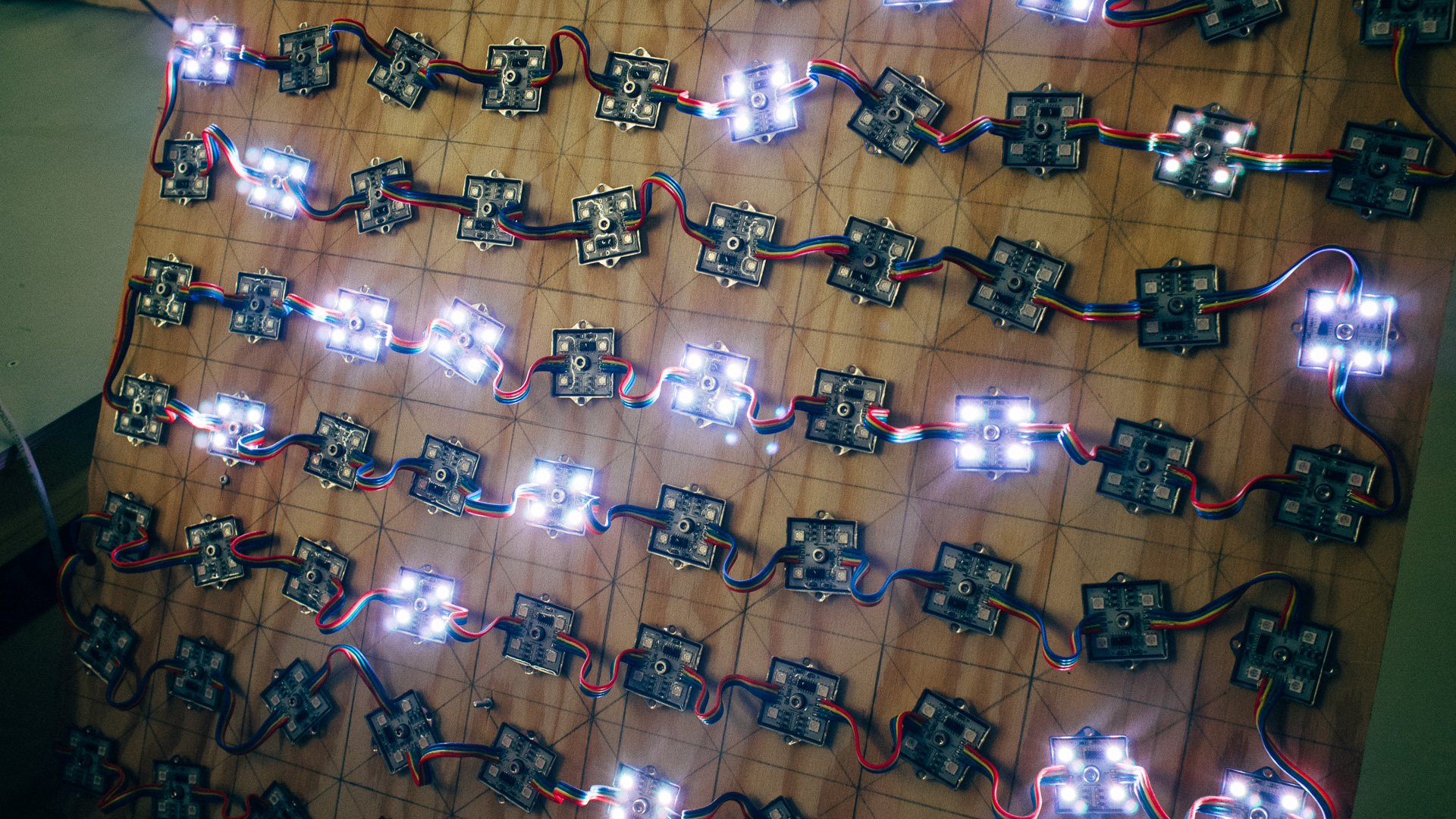
We came across this assembled LED board in our storage from a project we had a couple of years ago. It has 100 pixels in a 10 x 10 configuration with a WS2801 controller in each pixel. For those not familiar with such pixels it allows us to control each individually with their own red, green and blue intensities.
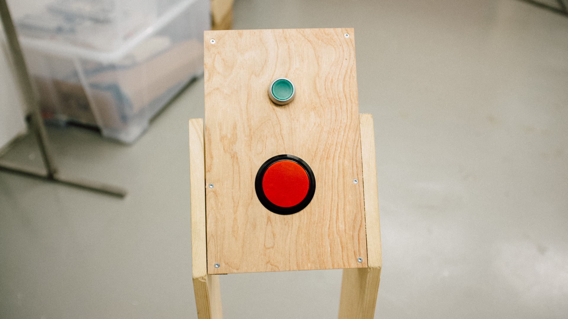
After a quick brainstorming session we decided to make a reaction game. A game where you should react to something as fast as possible. In our game it translates to following chain of events:
You start the game –> Random time –> LED board lights up, we start a stop watch –> YOU press the button, we stop the stopwatch
For simplicity to our visitors we only had one color on the LED board, such that you press as fast as you notice any light from the LED board. We might change this at a later time, with different colors and you where are only allowed to press on a certain color!
Building it
Now that we had decided what we were going to build, we needed to choose the key components.
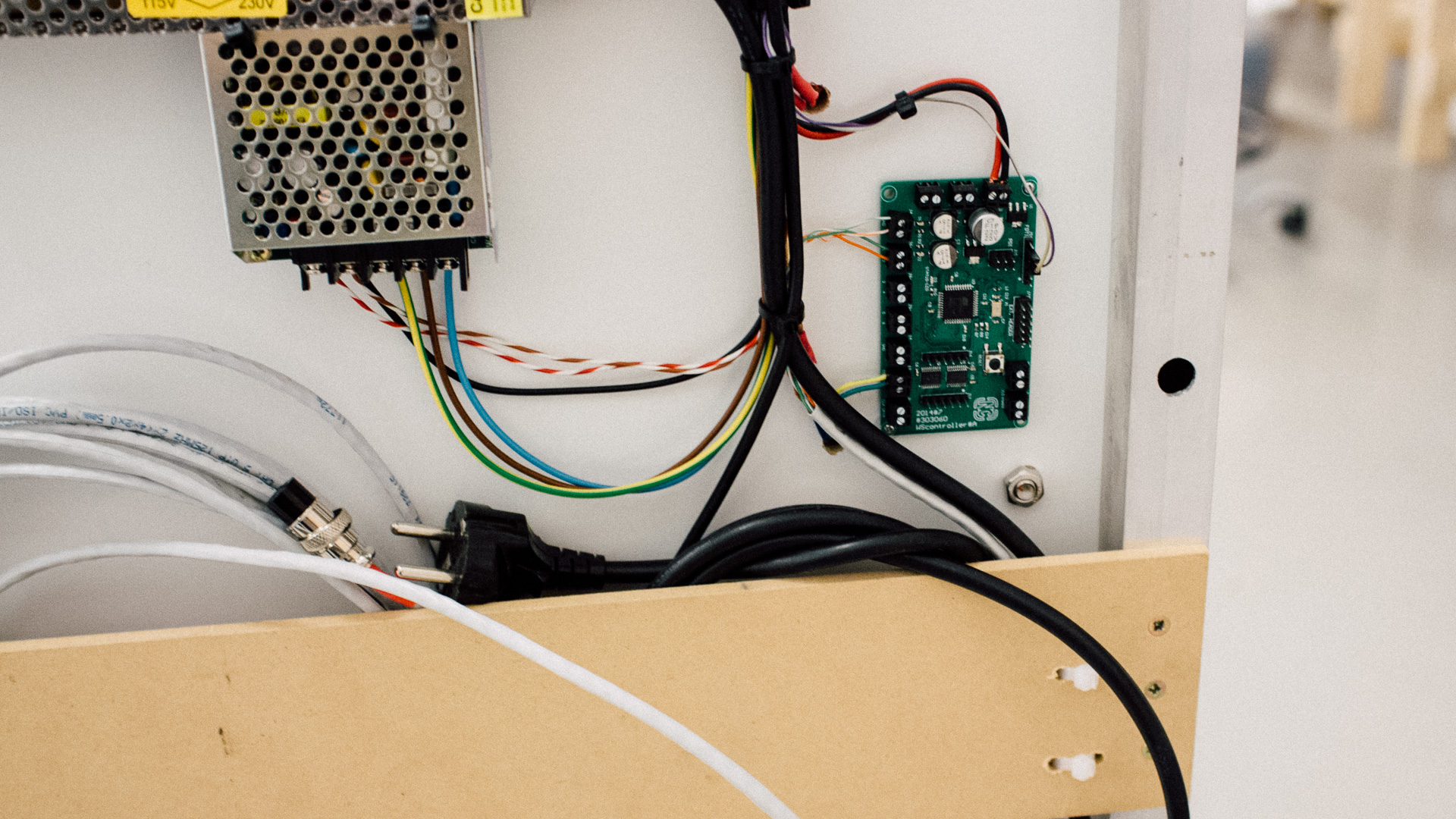
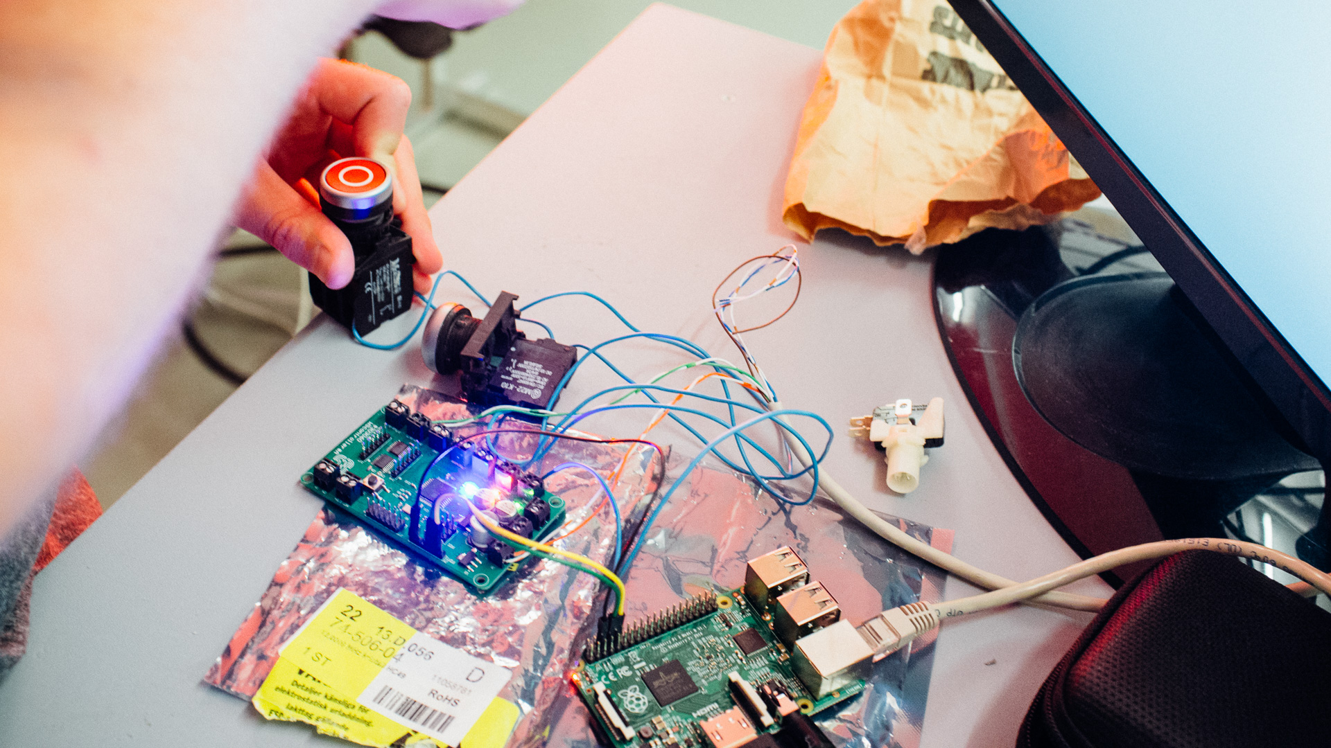
To control the LED board and measure the time, we decided to use a custom made PCB from an earlier project (this LED installation). This board has an XMEGA D4 microcontroller on board and electronics to properly buffer and drive signals for the LED chain. You can compare this board to an Arduino, in fact we could as well have implemented this on an Arduino instead!
The board have inputs for the buttons so that we have full control over the timing from when we light up the LED board until the button is pressed.
The code that is running on the XMEGA is written in C and is running “directly” on the core without any underlying support systems (operating systems or similar…). This enables us to have a deterministic system and we can easily have millisecond precision on our game!
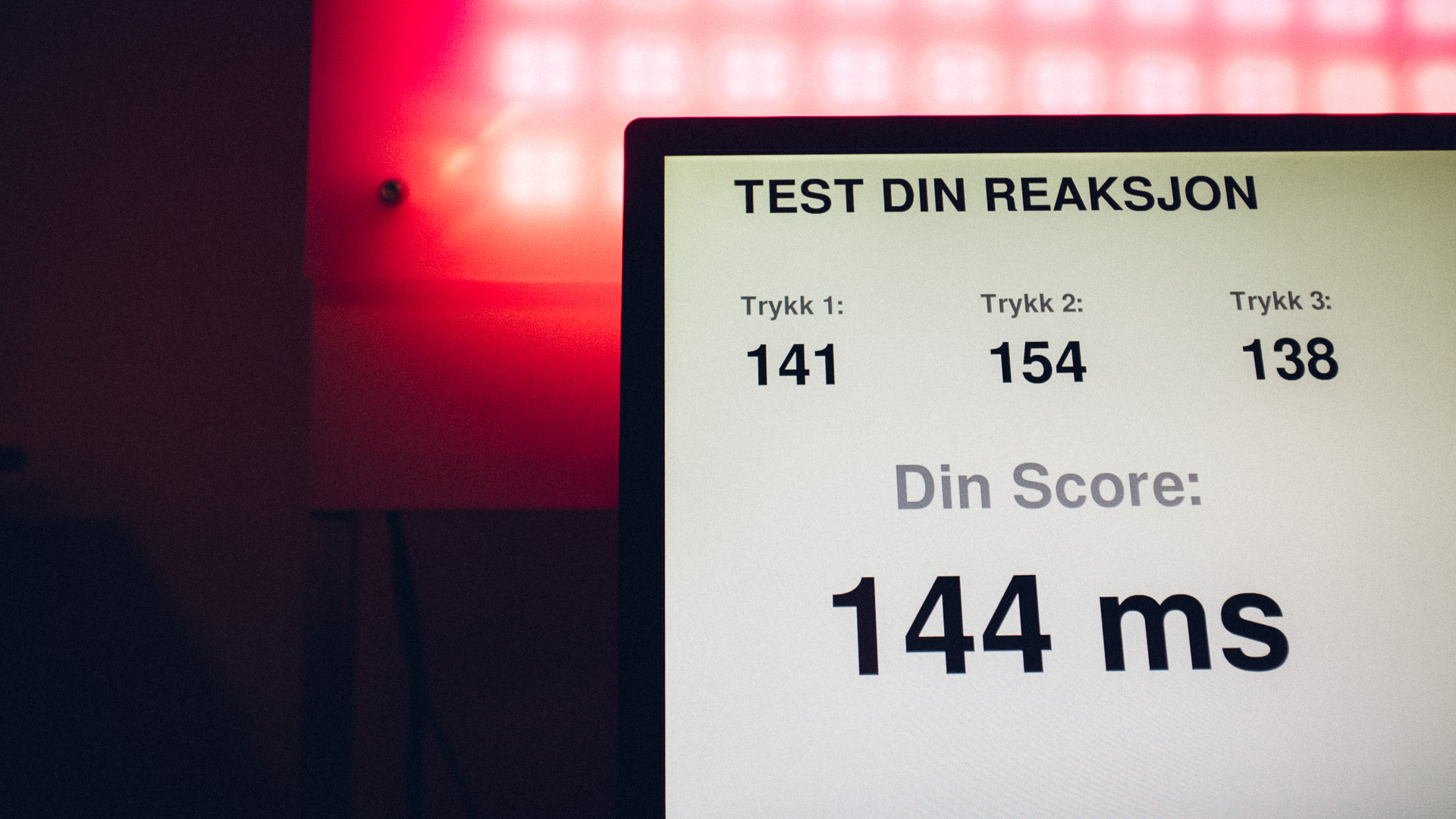
To spice up the “gameplay” we added sound effects and a screen were your score is presented. To easily do this in “no time” we added a Raspberry Pi 2:
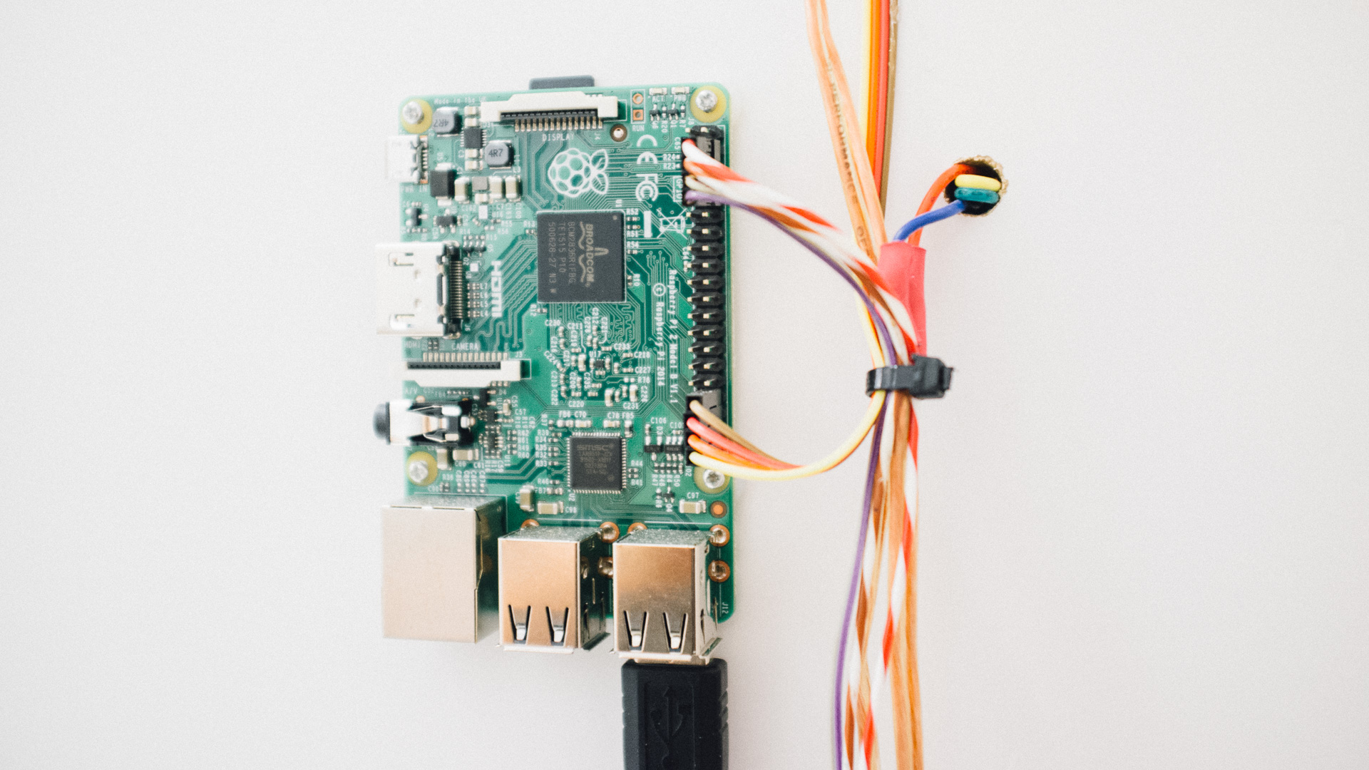
The simplest communication interface between the Raspberry Pi and our XMEGA board were UART.
So we implemented it with UART and a “low tech” custom made protocol. On the RPi we are running Raspbian and a Python script. The python script does the following:
- Establishes communication with the XMEGA board
- Plays sound effects on cue
- Displays current player’s score
- Displays a Top10 list of scores
- Stores all scores in a CSV formatted file
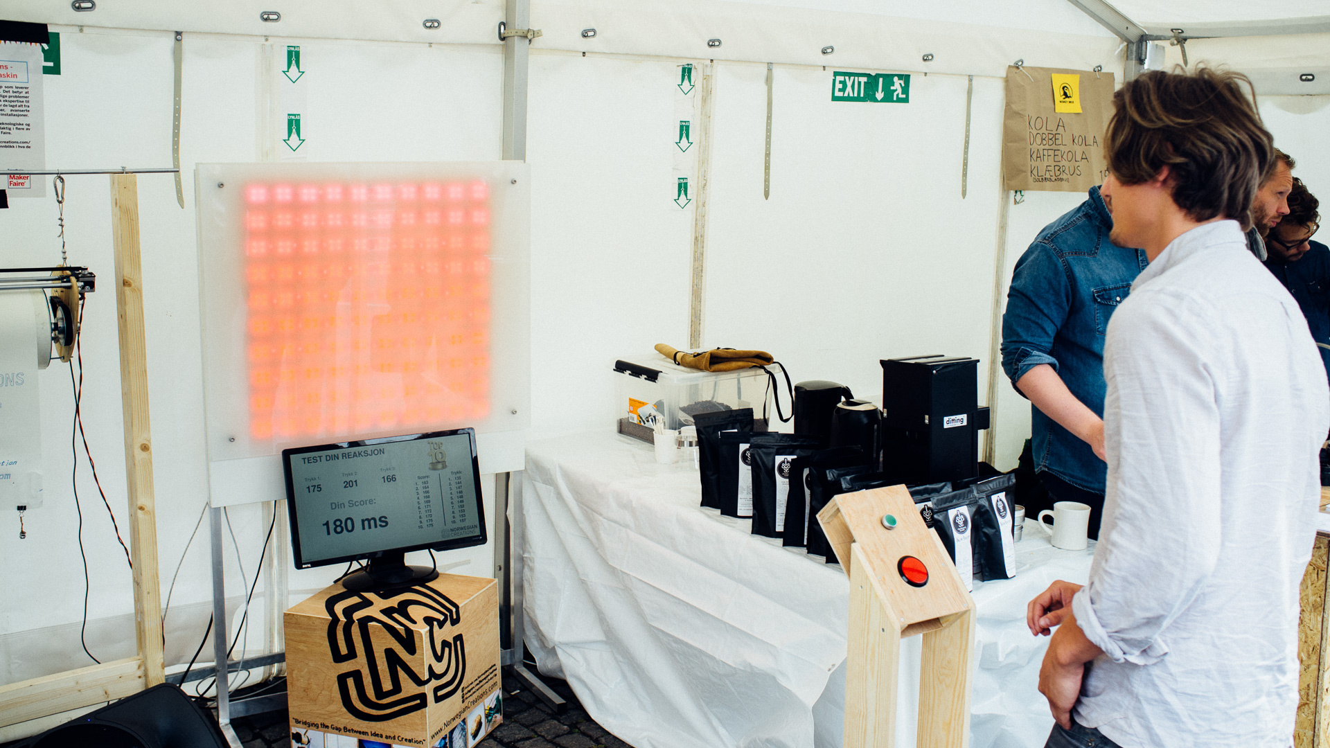
Here is parts of the finished layout on the score monitor:
To power the game we actually used two power supply units. In the upper middle in the picture below is a 12V, 15A for the LEDs and the XMEGA board.
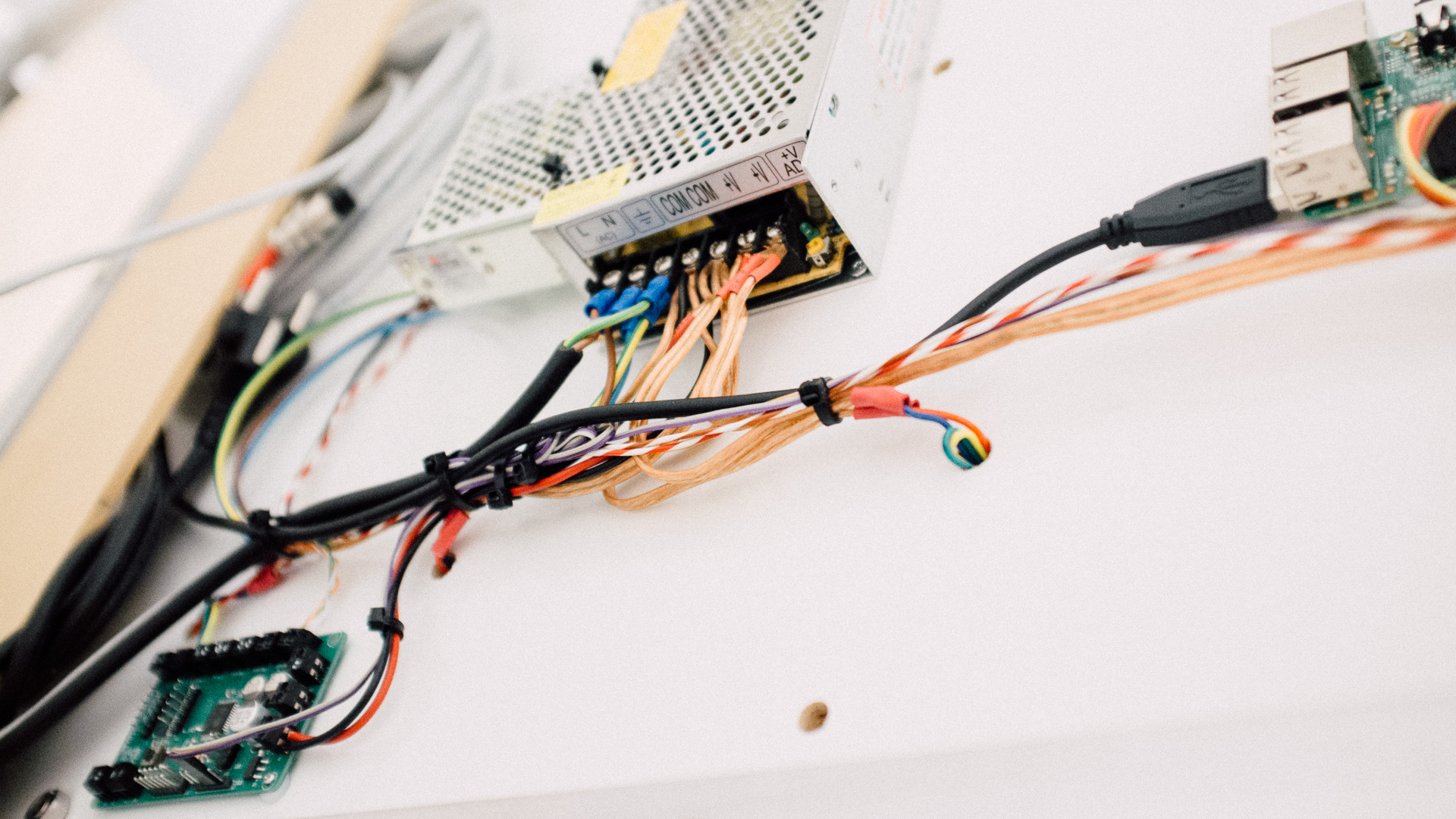
On the left you can see a smaller power supply mounted next to the larger one. That is a 5V, 2A power supply for the Raspberry Pi.
That’s it!
Here is a small “behind the scenes” video we have made:
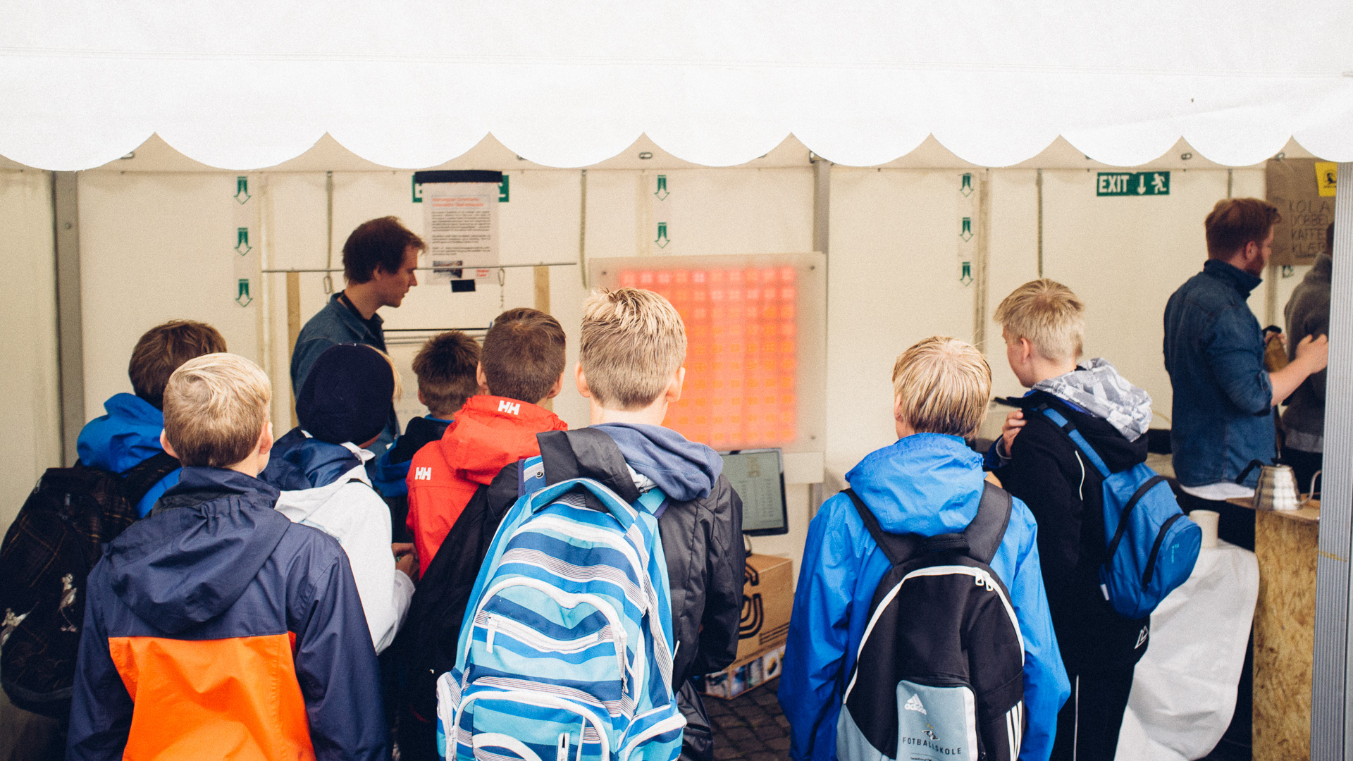
And some pictures from the Maker Faire: