This post will show you how to trace bitmaps in the free vector graphics software Inkscape.
Tracing bitmaps means that you convert a bitmap/raster image file (your usual .jpg, .png, .bmp etc) into vector graphics.
What are Vector Graphics?
Vector graphics are images represented by geometrical shapes such as lines and curves, instead of pixels as you find in .jpg and .png files. All of these geometrical shapes are based on mathematical expressions and can thus be manipulated as such.
Limitations and Attributes
Good representations of actual photographs and complex drawings are not things you want to use vector graphics for. The number of colors and the huge amounts of complexity will not be well represented within the vector domain. Vector graphics are however well suited for simpler images such as company logos or line drawings, to name a couple. Note that tracing is an approximation of the original image, so don’t expect to see 100% accurate traces of raster graphics.
Do a Google image search on “vector graphics” to see examples of what these can look like. What most of them have in common are smooth lines, crystal clear edges and rather simple coloring.
Why?
So why would you want to trace bitmaps? We have a few suggestions:
- Since everything is mathematically represented it is also “infinitely” upscaleable without having to worry about things getting pixelated. So if you have fetched a .jpg online which is too small for your application, you can trace it to vector, scale it up and then export it as a bitmap again looking better than ever (the .jpg compression noise will most likely disappear).
- Lines (nodes) within the vector domain are editable. If you have features in your image which need to be adjusted, you can drag the nodes around and edit the curves as you see fit.
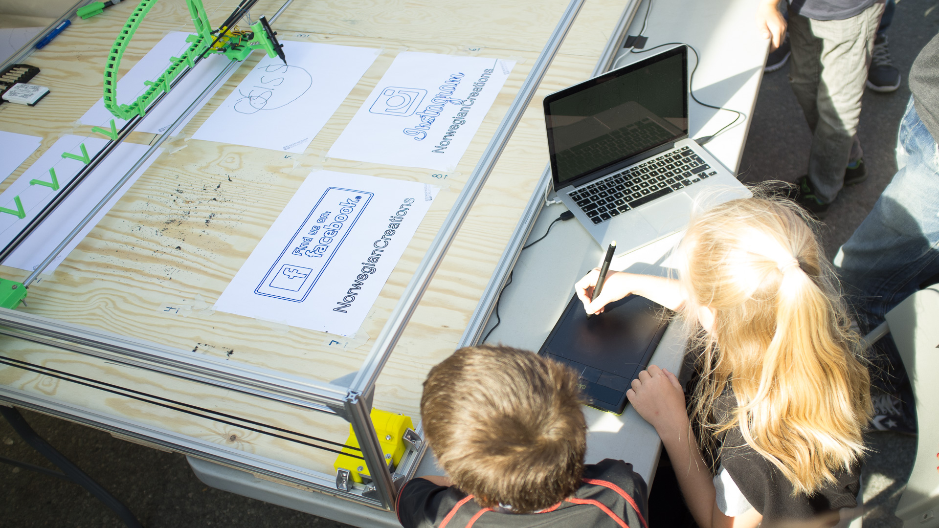
- This is our favourite reason to trace bitmaps. If you have a drawing machine or CNC machine for instance, you can trace a line drawing and create toolpaths for those machines to replicate the drawing. A drawing machine will then draw more like a human and less like a printer. We have used bitmap tracing for this purpose in this project (amongst several others).
How?
After you have installed Inkscape, import an image file you want to trace by clicking File and then Import. You don’t need to worry about the default frame in the main window.
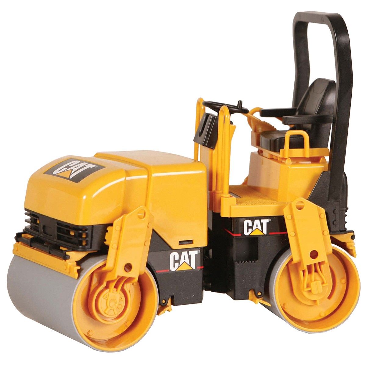
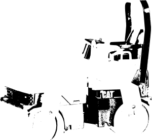
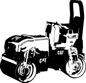
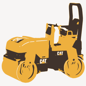
We’ll use this as an example image (as seen in last weeks post):
Under Path, select Trace Bitmap (#3 from the top). A new window will pop up. Have your bitmap selected, choose your tracing metod and press OK. The newly created object will overlap the old one, so just drag one of them to the side to gaze upon the result.
There are a few different tracing methods to choose from:
Brightess Cutoff (single path)
In this method, differences in brightness are considered an edge and thus a path. The threshold decides how many paths that will be created. The higher the number, the higher the amount of edges are detected.
By default, the areas within the paths are filled. If you want an outline along the paths instead, select your new object, enter the Fill and Stroke dialog (Object -> Fill and Stroke), select the x (“No paint”) under the Fill tab and select the Flat color button under the Stroke paint tab. For more in depth explanation on how to use this functionality, take a look here.
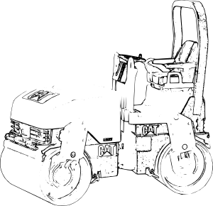
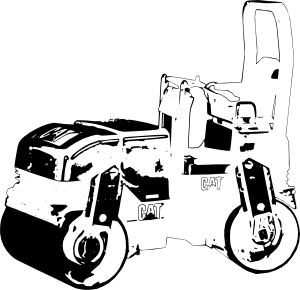
Edge Detection (single path)
This does a lot of the same as Brightness cutoff, but with a different algorithm. The lower the threshold number, the more edges will be included in the trace. The same thing with fill and stroke goes here as well.
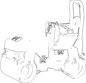
Color Quantization (single path)
A bit more complex method where the algorithm detects color changes instead of changes in brightness to find edges. These images are inverted (an option in the Trace Bitmap dialog) to give them a white background.
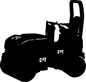
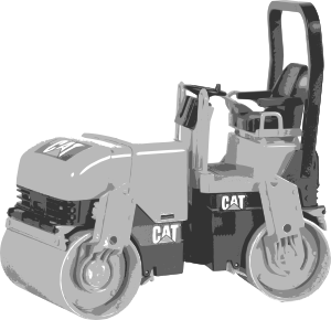
Brightness steps (multiple paths)
This method traces the number of brightness steps provided in the “Scans” field and creates a group of several paths.
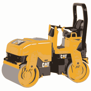
Colors (mulitple paths)
If you want to keep the colors in the image, this is the method to choose. The resulting number of colors is decided in the Scans field.
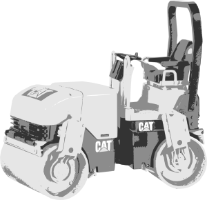
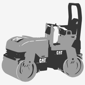
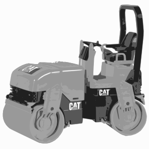
Grays (multiple paths)
The same as with Colors, except it is converted to grayscale.
Options and Tips
Under the Options tab you’ll find an option to supress speckels with a certain amount. This will exclude things like noise and compression artifacts from the trace.
The Smooth Corners option will do exactly that, where a higher value makes the corners even smoother.
The trace can often create way too many nodes to work with. Try simplifying by selecting Simplify under Path (or ctrl+L). This can be done several times to end up aproximately where you want to be. Sometimes the trace may even look better after a few rounds of simplify.
To get the result you want, we suggest that you try experimenting with different methods, thresholds and other parameters. A bit of tweaking here and there can do wonders!