Be sure to read part 1 where we talk about the design phase of this installation!
Mechanical and Structural
CNC-Milling
As in this project, we had to utilize our new CNC-milling machine, and the upright plywood pieces on the back of this installation were actually the very first parts we milled out.
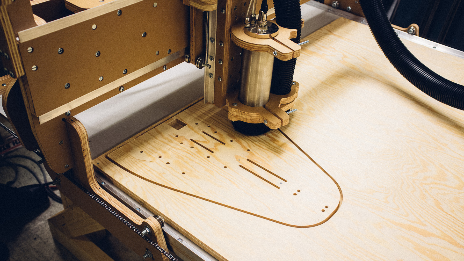
We also had to mill out several other smaller pieces of plywood as well as the bottom and top frame of the tank.
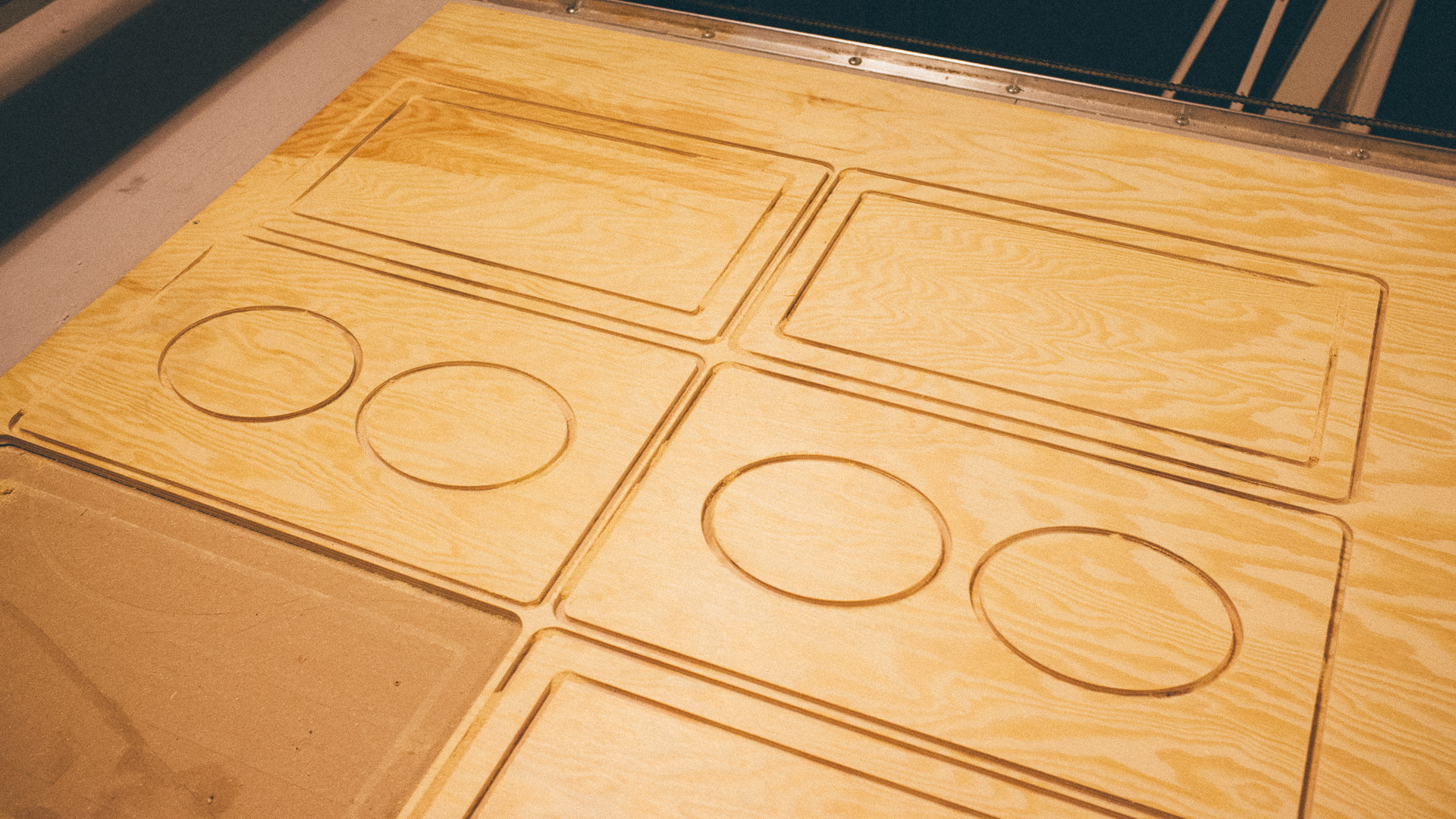
Milling plywood is relatively quick and easy to do. After a while we started using Cut2D for these kind of milling tasks instead of CAM’ing it in our CAD software. It’s very easy to set up and use and everything is in 2D so only vector graphics are required in the software.
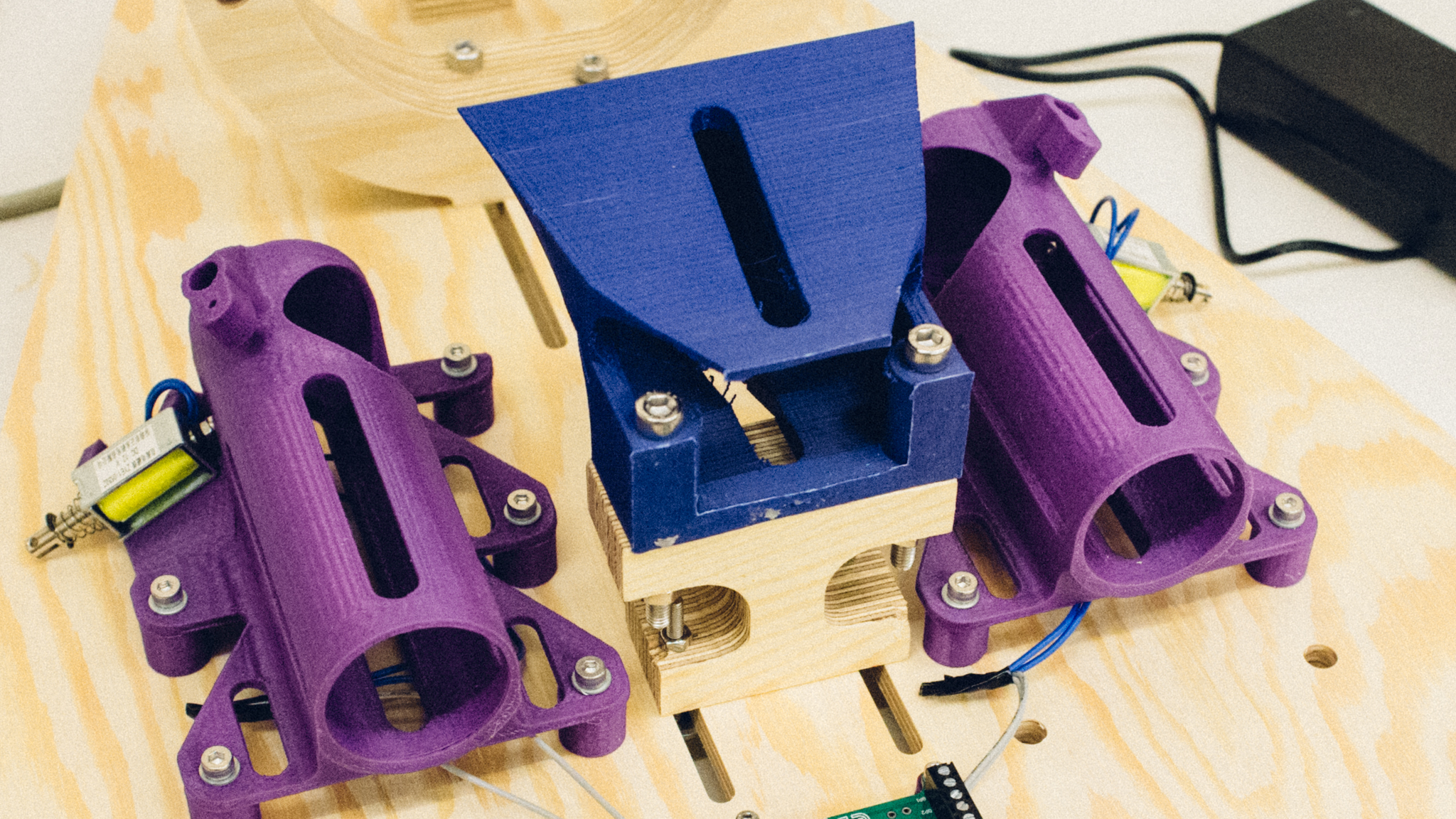
3D-printing
This project had a really demanding amount of pieces that needed to be 3D-printed: 8 funnels, 8 dispensers and 4 deflection prisms as well as 8 servo rods and a terrifying amount of spacers with inserts.
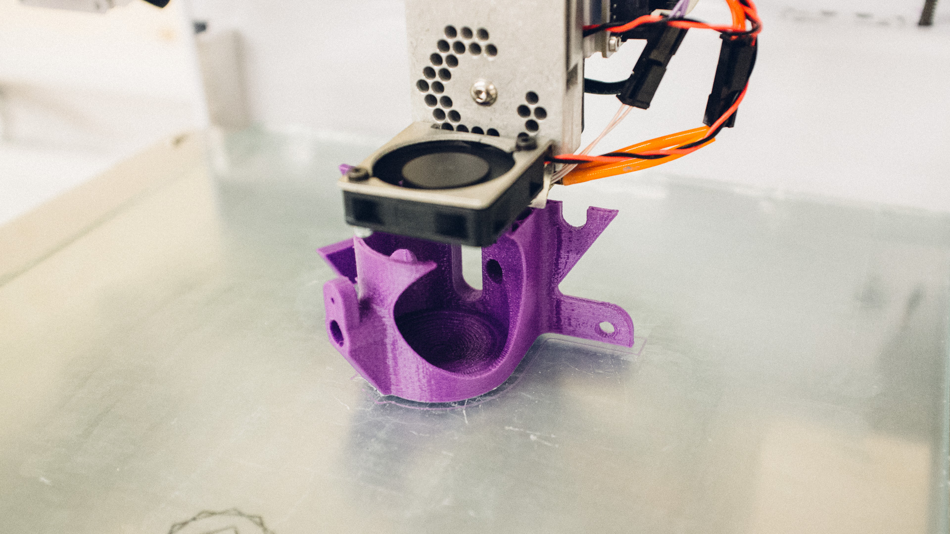
We used our new Type A Series 1 3D-printer for the dispensers and the funnels, printing them in PLA. For the prisms we used the good old Solidoodle 3 which we’ve had for several years now. The Solidoodle prints ABS material.
To make the PLA pieces stick to the Type A print bed we use an ordinary glue stick, as opposed to the ABS parts where the heat in the print bed make the pieces stick. Getting the PLA pieces off again has proven to be a more difficult task than making them stick (many would call this a luxury problem). Another issue we had was adjusting the ideal current for the stepper motors on the Type A. Sometimes they would miss a few steps, resulting in a somwhat skewed model. After a bit of tweaking we managed to get the printer working without any major issues and suddenly one piece after the other was steadily popping freshly out of both the 3D-printers.
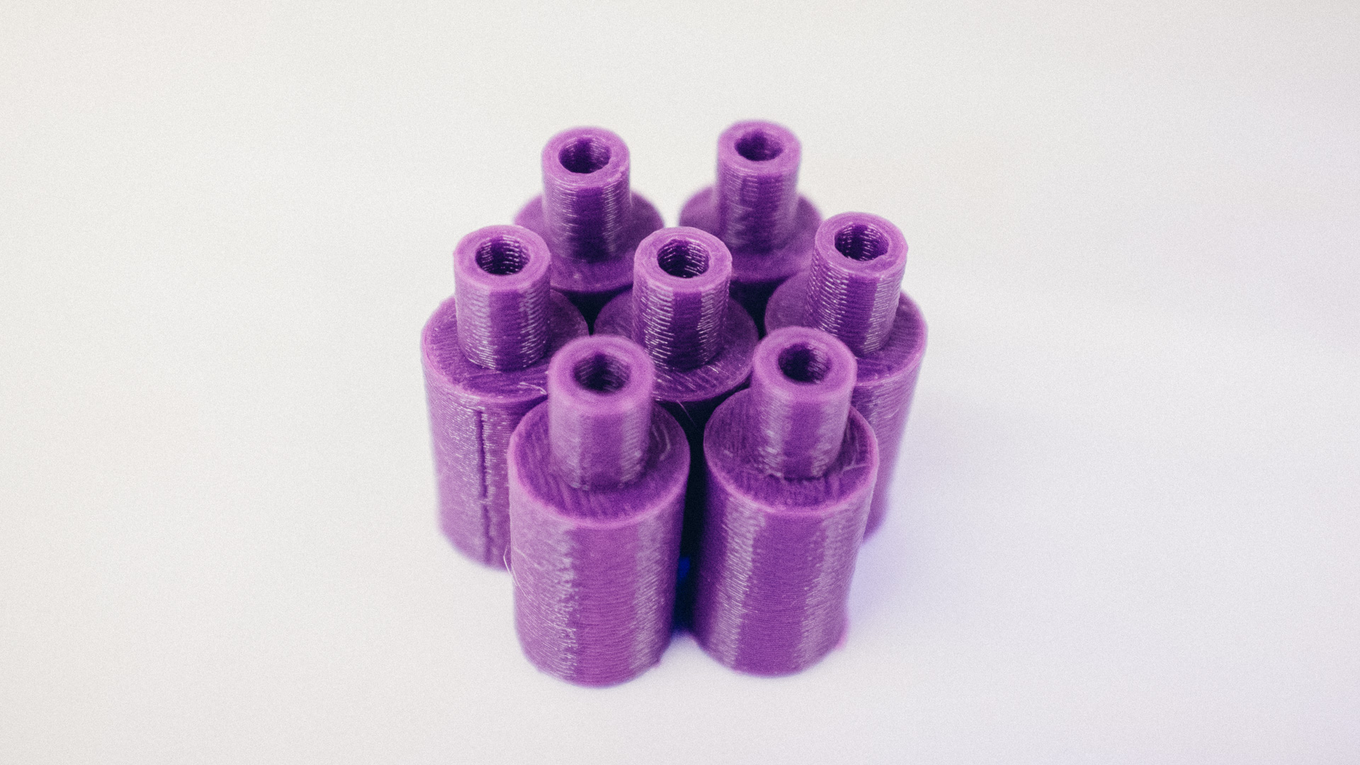
Mounting
Many parts needed to be mounted on all four plates.
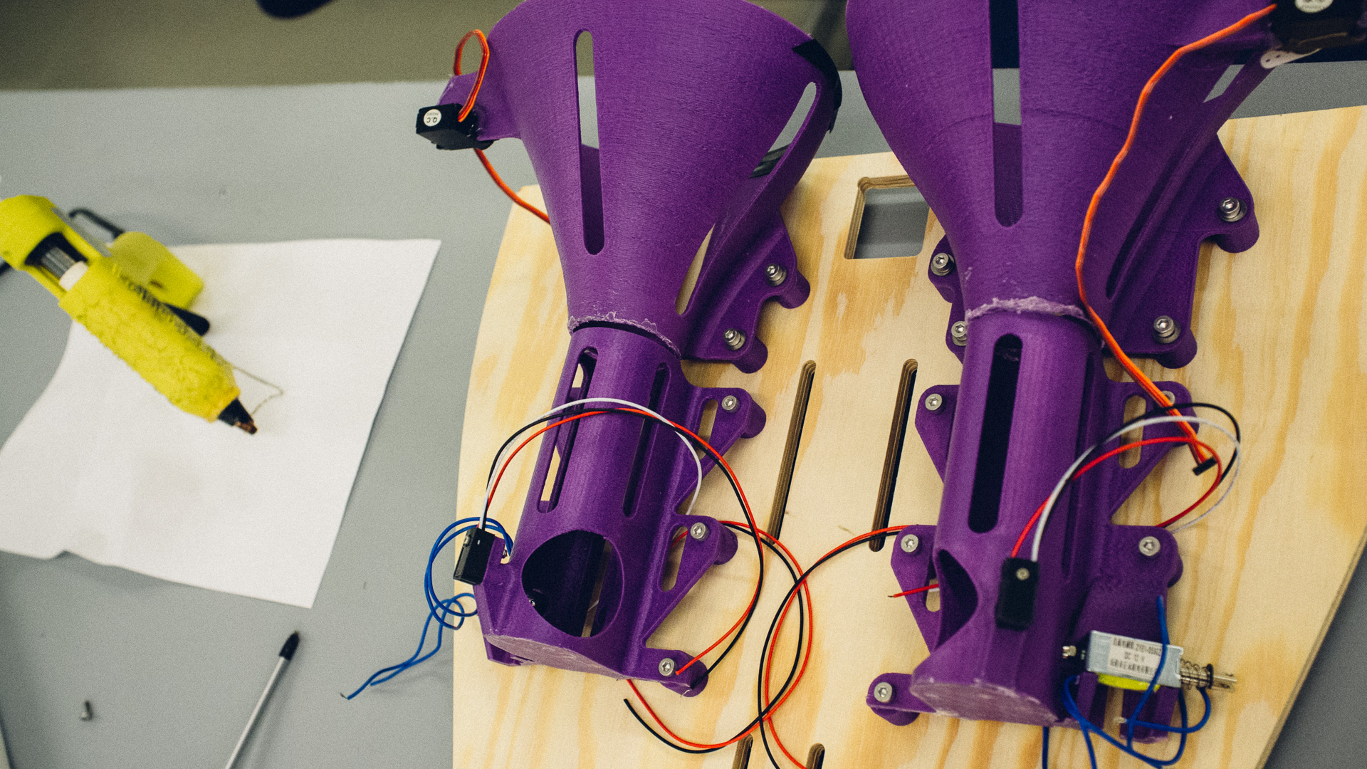
The funnels and dispensers neded to be spaced a bit away from the back plate due to the nature of their design. For this purpose we designed and 3D printed our own spacers. At the time we didn’t have endmills for the CNC to drill small enough holes in the back plate for the bolts, so we made the holes a bit larger and added some inserts on the spacers such that the inner diameter fitted the bolts and the outer filled the holes in the plywood.
More Plywood
As mentioned in the CNC part, we milled out some smaller plywood pieces as well. These were used as different types of brackets, both for mounting the prisms to the back plate as well as fastening the back plates to the pipes. Some of these brackets were two similarly milled out plywood pieces glued together (as a sandwich) to make the brackets twice as thick as the original plywood thickness.
In the very top of the image above you can see some of the bracket which rest on top of the pipe. We glued on wooden pegs underneath it, which would surround the top of the pipe, preventing the whole thing from falling off.
For easy and continous height adjustment of both the prism and the top of the pipe relative to the backplate, we had milled out oval slots seen on the picture above.
Furthest down on the back plate we had another small plywood bracket. This was laying flat between the backplate and the pipe with holes through it on the sides for zip-ties. These zip-ties would be fastened around the pipe ensuring that everything on the top was fastened properly.
Software and Electrical
Electronics
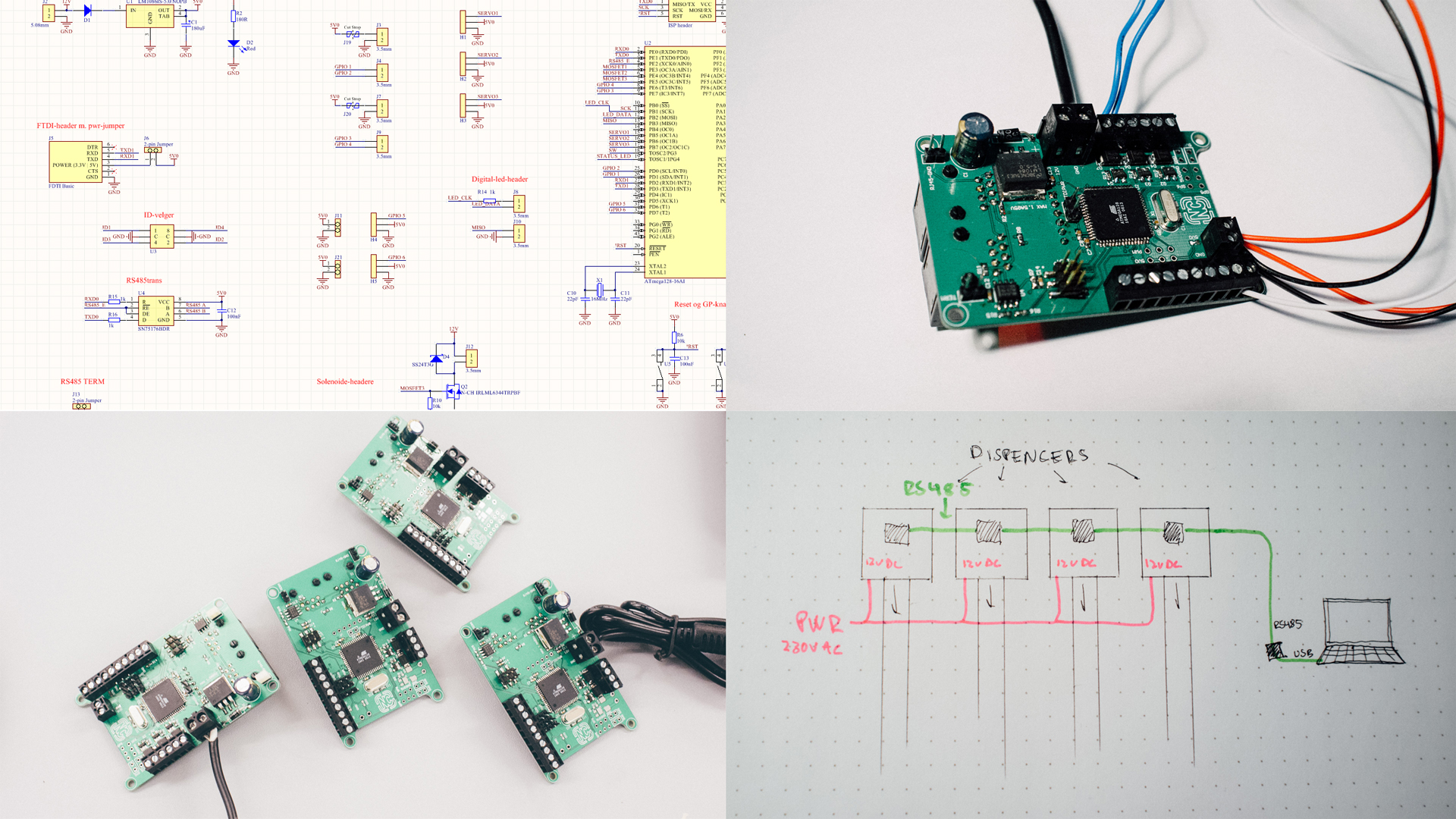
Each of the four dispensers had exactly similar PCBs running the same firmware.
We equipped the PCB with among other things:
- A local linear PSU able to deliver 1.5 A at 5 V
- An ATMega128 running at 16 Mhz
- An Half-duplex RS485 transceiver including stuff such as optional termination
- Control circuitry for solenoids, servos and LEDs
- Misc. input and output for further expansion
Instead of making two different PCBs, one for controlling a dispenser and another for making it possible to connect this system to a computer, we added the functionality necessary for using cards as the RS485 <-> USB bridge for the controller.
Each of the controllers run the same firmware, and we attached a rotary position switch for setting each modules unique network ID.
Software
The system was controlled over cable (RS485) from a control computer. Here it should be possible to controll different aspects such as shooting balls, turning on/off LEDs and running servos.
We created the RS485 protocol ourselves, but it sure inherited several great features from several “workhorse-protocols”
This is a single-master-multiple-slaves protocol. The master is the only one that can initiate communication. Each packet includes things such as a checksum and a type-description.
To make it easy to control the system, we hacked together a quick-and-dirty control panel in Python using TkInter. This did NOT have to look pretty. It just had to do the job.
The screenshot below shows the control panel before event start. It consists 40 buttons (10 for each dispenser), and a bunch of status fields. These status fields (under each button) gets filled with numbers when different things happen.
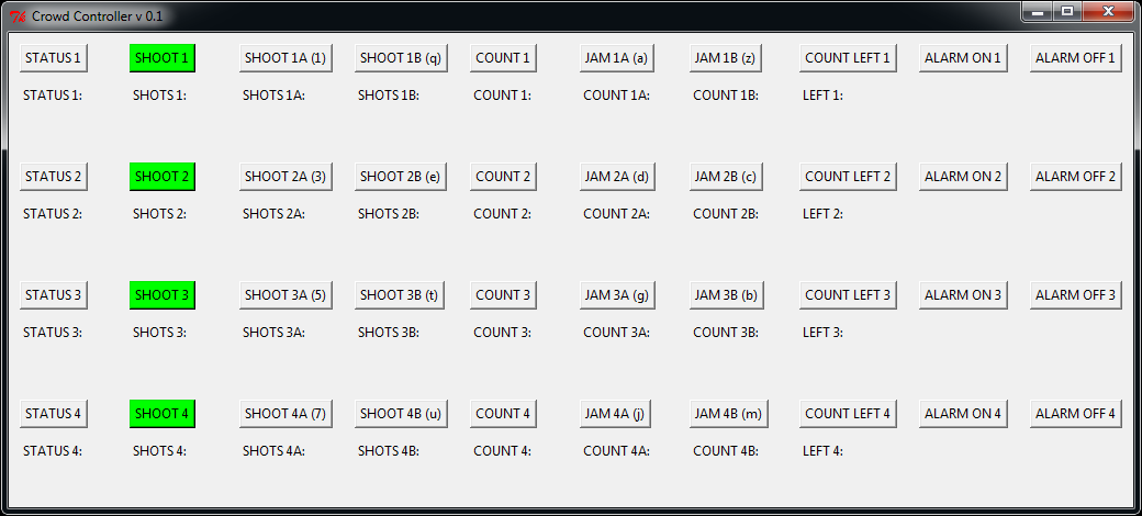
This control panel can be directly controlled by the crowd funding software platform, but since this was a rather complex event, we decided to control the timing of the different events ourselves.
So we did need to constantly monitor the 4 different campaigns, but it was worth it, since we could dispense ping pong balls at the exact perfect moment in the scene show.
A Short Conclusion
This project seemed rather simple, but in fact, it was quite the challenge. It was also really fun since we were able to use all our crazy creativity to make it as we wanted it to be.
Manipulating physical objects (such as these ping-pong balls) always adds additional challenges to the design and implementation, but we were able to solve them and deliver a working product which we’re very satisfied with!