This post contains a review of different aspects of the Laser Engraver. And it will probably be updated continuously.
System overview
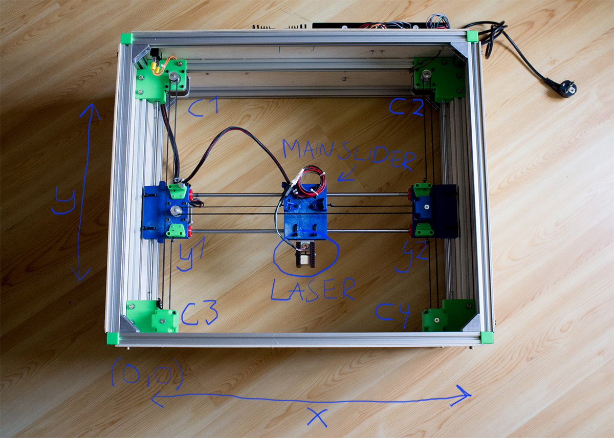
Just to start out on the right foot, this image explains how we name all the different main parts of the machine:
Mechanical solutions
The frame
The frame consists of 20mm aluminum extrusions. The market is packed with different types of extrusions, so it can be difficult to know where to begin. Just ordering something and start playing with it is the right thing to do here:) And thisblog-post will help you out!
For the minimum frame we ordered these parts from Misumi Europe:
- 2 * HFS5-2020-510 (51cm)
- 2 * HFS5-2020-600 (60cm)
- 4 * HFS5-2020-300 (30cm)
- 1 * HNKK5-5: M5 Pre-Assembly nuts (Box of 100)
- 8 * HBLFSN5: Reversal Brackets with Tab
And when we upgraded the frame, by adding a top and bottom floor, we just added:
- 4 * HFS5-2020-510 (51cm)
- 4 * HFS5-2020-600 (60cm)
- 12 * HBLFSN5: Reversal Brackets with Tab
And you need M5 bolts to put the frame parts together.
Linear motion
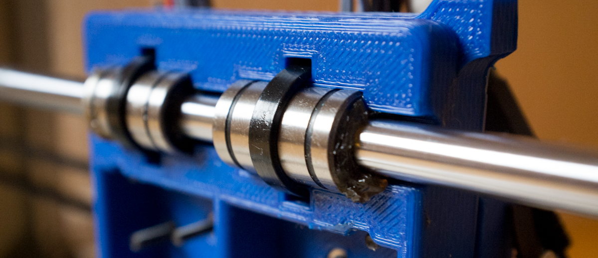
The linear motion is supported by 50 cm long 8mm linear rods. 50cm is maybe the longest you should go when using only 8mm rods. Since the traveling parts is rather light, 8mm goes here, but you should upgrade that if you are making something heavier.
On the rods we use a total of 8 LM8UU linear ball bearings. They are also from a rather cheap vendor. So quality is not top, but it’s an okey start. Easy to change later..
This whole motion system is hold up in the frame by the 3D-printed parts.
And remember to use some sort of grease. Do not use WB40 (or that kind of lubrication products).
Motors and motor drivers
We use NEMA 17 motors in this machine and yeah: Overkill. But we had several lying around.
The two motors that move the y-slider are wired in parallel (C1 and C2). Note that the two coils are swapped so they move in the opposite directions. We have no position feedback on this system so we are totally dependent on not loosing any steps. And large motors helps us out with that..
The motors are driven by two DM542 stepper motor drivers. There exist many better and faster drivers (such as Geckodrive), but the DM542 drivers get the job done.
At the moment we run at something like 70 steps/mm. More information to come!
Belts an pulleys
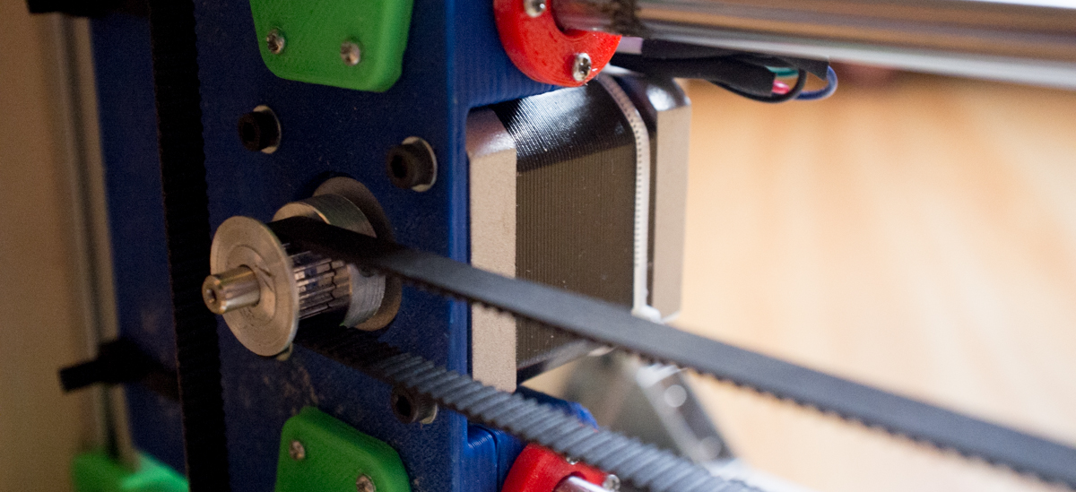
There exist a lot of different belt and pulley types. MXL belts are used on a lot of different 3D-printers, so we went for that. GT2 belt are probably better (less whiplash), but they are of course a lot more expensive.
So we ordered 10 meters MXL belt and some appropriate pulleys.
The 20 teeth MXL pulleys (should) have a pitch diameter on 12.93mm, meaning that one revolution will move the belt π*12.93mm = 40.62mm.
NOTE: We are dependent on that the two y sliders (y1 and y2) are driven exactlyalike. So the motors has to run alike AND the two pulleys on the motors has to be identical. We thought of course that they were. But they were not…
A difference in only 0.15 mm outer diameter caused this error:
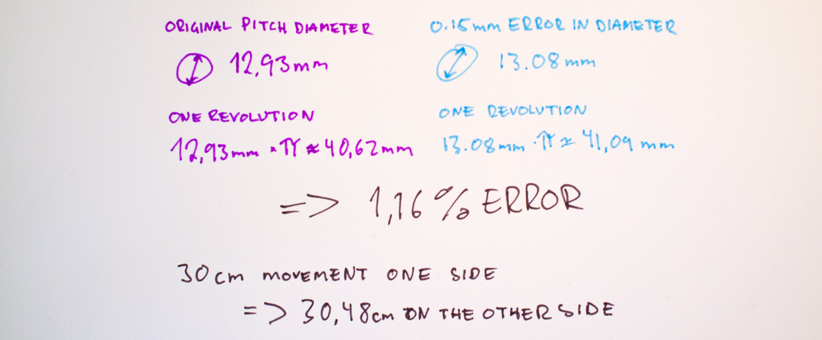
So when the machined had moved 30cm on one side in the y-direction, the other side had moved 4.8mm more! And that is easily notable. When we found that the error was caused by the pulleys, we did a “meassure-them-all” and found two that matched pretty good.
NOTE: If you want two things that should be exactly alike, you should think about that when you look for a supplier.
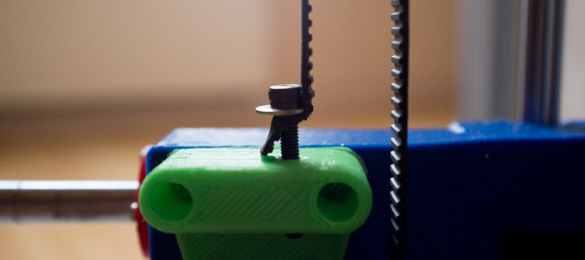
The method used to attach the belt to the different sliders should be quite stable and also give the operator an easy way to adjust the belt tension. We were inspired by the method used on our Solidoodle 3D printer. The method consists of some long M3 bolts attached to the belt through a small hole. The belt is protected against bolt head friction (from when adjusting the tension) with a small washer. And belt tensioning is as simple as turning the bolt.
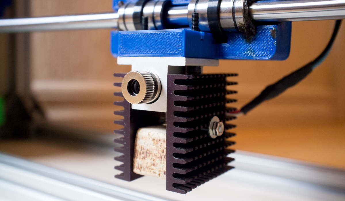
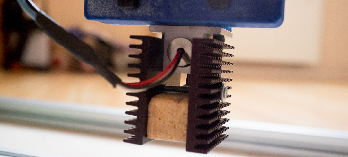
Laser
The whole machine is built around the fact that small power lases diodes is small enough to carry around. Compared to “real” laser cutters, where the laser is stationary and mirrors is used to move the beam, this is a lot easier to design with. And by using a rather small laser you can get away without active cooling.
We use a 445 nm 2W laser at the moment (ordered from ebay). But we are going to change to a 405nm, because it’s (probably) easier to get it super focused.
To drive the laser we just use a cheap constant current driver right now. The driver is only capable of supplying the laser with a total of 0.5W power.

This whole laser chapter is the first thing to be modified. Both in the driver and laser department…
Safety
LASER SAFETY IS IMPORTANT! READ THIS GREAT FORUM POST!
The plan was to cover the whole machine with an approved safety glass. After getting some quotes, we decided that it was way to expensive. So the plan now is to make a small window in the plywood instead.
But we also needed safety goggles for testing and development. So we ordered these. Do not be stingy here!
Electronics
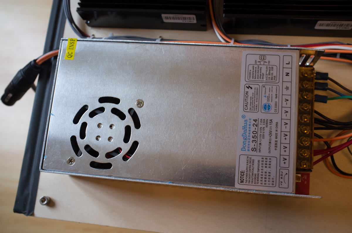
Power Supply
The stepper motor drivers needs a minimum input voltage on 24 volt so we use this as the main power supply.
The main board has an internal linear regulator supplying the board with 5 volts. But since it has to take down the voltage from 24 volt, it gets rather hot. Therefor, as a quick fix, we placed two more linear regulators (24V->12V and 12V->9V) in series between the main supply and the card. These regulators where placed on a heat sink.
Yeah, the efficiency on the main board power supply is something like (assuming that the main card use 150mA):
(5V*0.15A) / ( ((24v-5V)*0.15A) + (5V*0.15A) ) = 21%
Not an efficiency worth writing home about. But that doesn’t matter. Wasting about 3 watts in heat is not our largest challenge.
Controller card
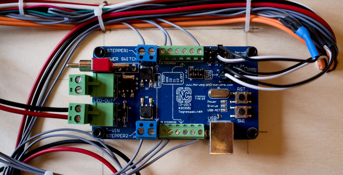
As the main controller card we use a PCB designed for the drawing machine. It’s driven by an AVR Atmega128 witch runs at 16Mhz. So a common Arduino board can fulfill its job.
The only thing it needs to do is to buffer some G-CODE, decode it, control the motors and laser and monitor some buttons. In other words, not so much. Read more about the software some sections down.
But since the card is taking care of all the motor timing, you can quickly run into a speed problem. By that i mean if you run at a high amount of steps/mm, and try to move really fast, the card cannot keep up with the pulse speed. And since the timers run at 16Mhz the maximum pulse speed is 8Mhz.
The maximum move speed: 8Mhz = steps/mm * mm/s.
With 500 steps/mm that is 16000 mm/s.
And this is an under-estimate. Because the processor has a lot of different things to do than to handle the timer ISRs.
But if you are not going to move really fast and/or calculate a lot, a “low-speed” 8-bit MCU will manage this job.
Software
On the controller card
The controller card runs GRBL. It’s written for Atmega162 and Atmega328, so we did a quick port to make it compatible with the Atmega128.
We mapped movement in the Z direction to the pin controlling the laser. At this moment the laser is just on/off. So when the machine is commanded to move the Z down, it turns on the laser, and when it’s commanded to move the Z up, it turns it off.
On the computer
Since the machine accepts regular G-CODE you can use a lot of different applications.
At the moment we export DXP files (ROBO-format) out from Inkscape. The DXP files is then imported into HeekCNC which converts the files into G-CODE. Read more about that step here.
To send the code to the machine you can use any Serial Terminal capable of sending a file (e.g. Hercules). At the moment we use GRBL Controller, which give us a nice visual feedback from the machine.
This post will be continuously updated, and if there is something important you think is missing, tell us about it!